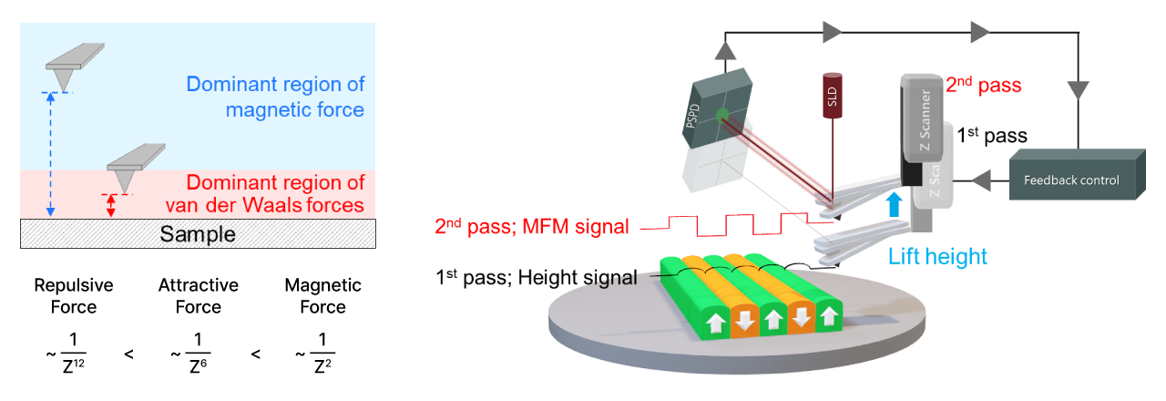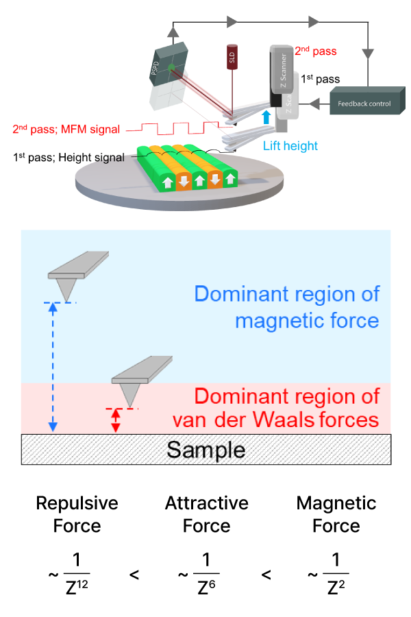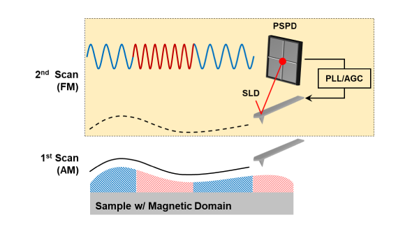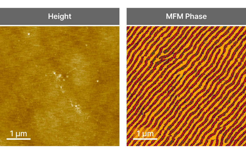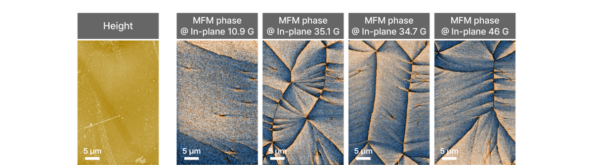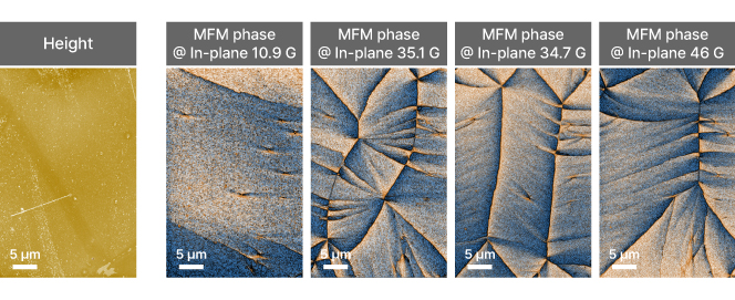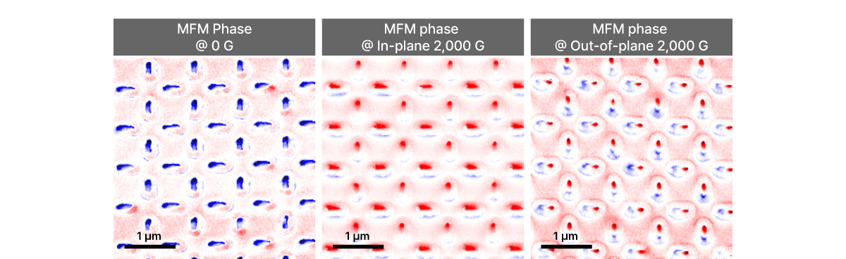
Magnetic Force Microscopy
MFM
Magnetic properties imaging by sensing magnetic forces between a magnetized
AFM tip oscillating above the sample surface